Available starting with FlowX.AI 5.3.0: Workflow data models enable integration between processes and Integration Designer workflows with structured data models at the workflow level, similar to Process Definitions.
Overview
Structured Data Management
Define entities, attributes, and custom data types at the workflow level, similar to Process Data Models
Input/Output Parameters
Specify which data enters and exits your workflow with automatic parameter management
Process Integration
Map data bidirectionally between processes and workflows using data mappers
Type Safety & Validation
Define data types and validation rules to ensure runtime data integrity
Key concepts
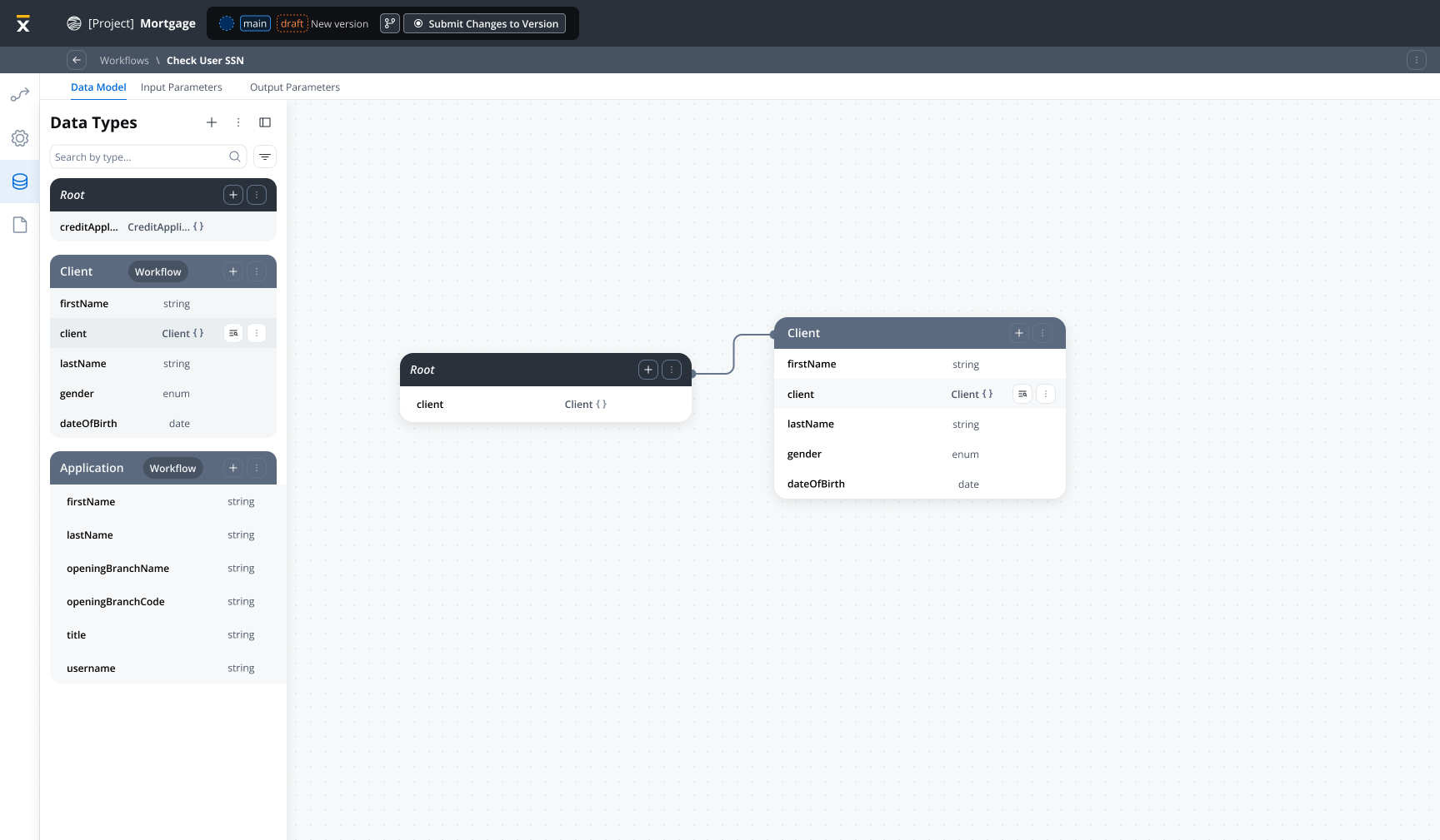
Workflow data model
A Workflow Data Model defines the structure of data used throughout a workflow’s execution. It consists of:- Entities: Logical groupings of related data (for example, Customer, Order, Payment)
- Attributes: Individual data fields with types and constraints
- Input Parameters: Subset of the data model defining workflow input parameters
- Output Parameters: Subset of the data model defining workflow output parameters
Workflow
Workflow parameters are defined in the data model that define which data is passed as input or returned as output:- Input Parameters: Automatically pre-fills the Start Node with structured data when you open the workflow diagram tab or test the workflow at runtime
- Output Parameters: Defines the data structure returned by End Nodes. Currently, output parameters work as-is (you can manually configure them), but automatic pre-filling from output parameters is planned for future releases
Node name uniqueness
When you rename nodes, the system validates uniqueness. If a duplicate name exists, an index is automatically appended (for example,Transform, Transform_2, Transform_3).
Creating a workflow data model
Navigate to Workflow Settings
Open your workflow in Integration Designer and navigate to the Data Model tab in workflow settings.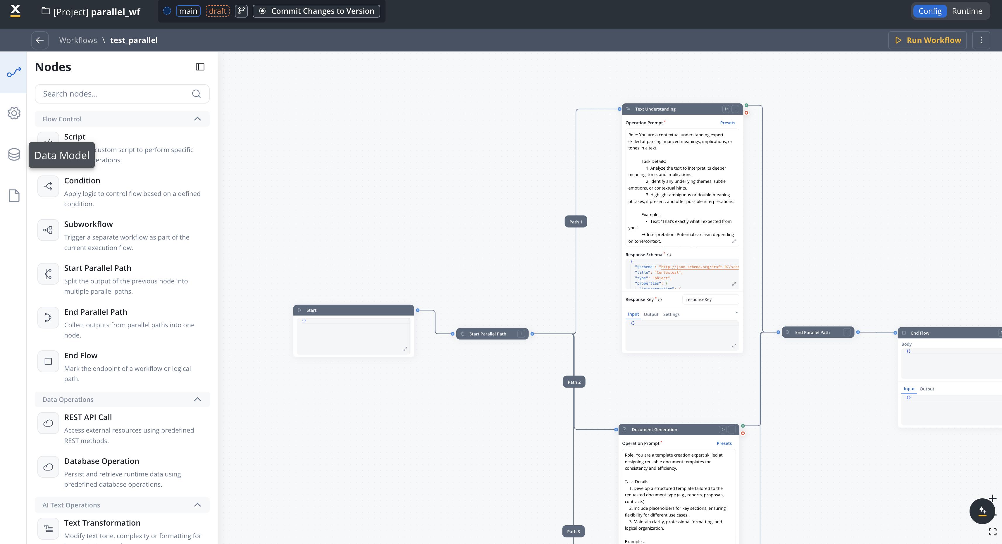
Define Entities
Create entities to represent the logical data structures in your workflow:
- Click Create Attribute
- Enter an entity name (e.g.,
Customer,Order) - Add a description for documentation
Add Attributes
For details on adding and configuring attributes for your data model—including data types, required fields, validation, and advanced options—see the Data Model documentation.
Configure Input Parameters
Define which data will be passed as input to your workflow: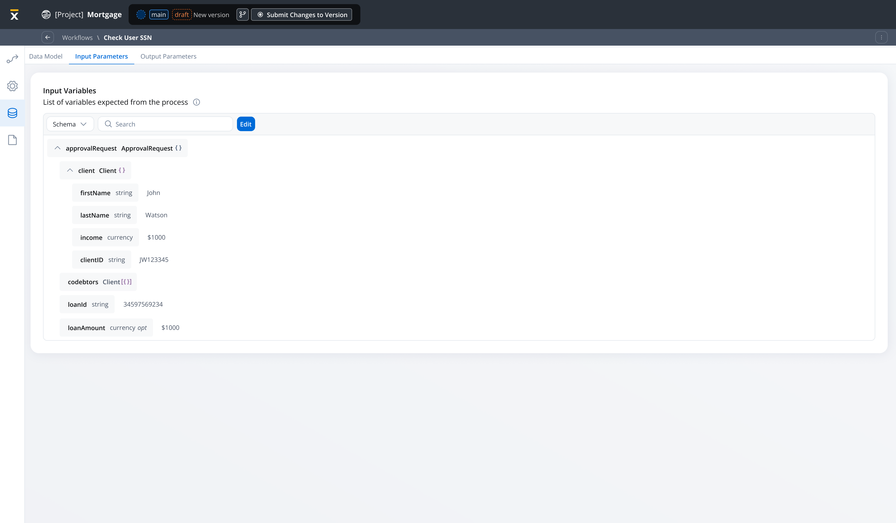
- Navigate to Input/Output Parameters tab
- Click Define parameters in the Input section
- Select attributes from your data model to include
- Mark required parameters
Input parameters data automatically pre-fills the Start Node when you open the workflow diagram or test at runtime.
Configure Output Parameters
Define which data will be returned when your workflow completes:
- In the Input/Output Parameters tab, scroll to the Output section
- Click Define parameters in the Output section
- Select attributes from your data model to include as outputs
- These parameters define the data structure returned by End Nodes
Output parameters are used when mapping workflow results back to the calling process via the Receive Message Task.
Input parameter management
Automatic start node pre-filling
When you define input parameters, the Workflow Start Node is automatically populated with the structured data:
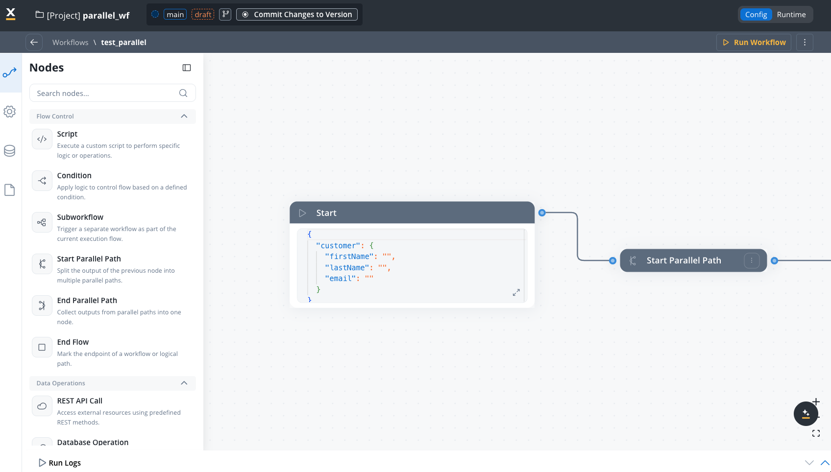
Empty input parameters behavior
If no input parameters are defined for a workflow, the Start Node contains an empty object ({}). The input parameters are optional, but defining it provides better structure and type safety for your workflow inputs.
Benefits of input parameters
No Manual Editing
Input parameters automatically pre-fill the Start Node - no JSON editing needed
Type Safety
Data types are enforced at the workflow level, preventing runtime errors
Clear Contracts
Input parameters document exactly what data the workflow expects
Easier Testing
Test workflows with structured input data based on the data model
Integration with processes
Process to workflow data mapping
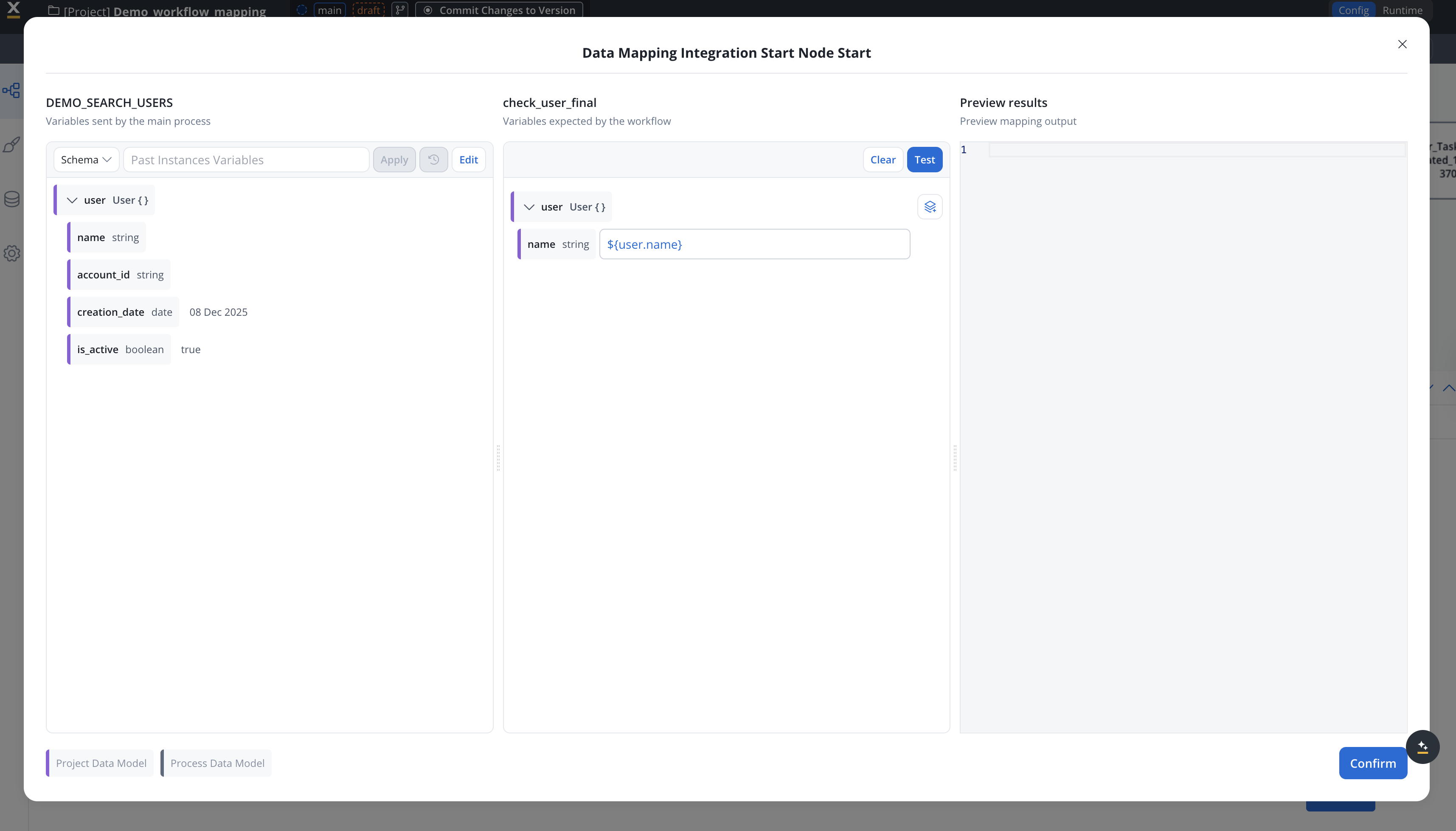
Use data mappers to pass data from processes to workflows. The data mapper configuration in the Start Integration Workflow action maps process data to workflow input parameters, independent of the workflow’s input parameters definition.The workflow’s input parameters are used for:
- Pre-filling the Start Node when designing/testing workflows
- Documenting the expected input structure
Add Start Integration Workflow Action
In your process definition, add a Start Integration Workflow action to the node where you want to invoke the workflow. Choose the workflow you want to invoke from the dropdown.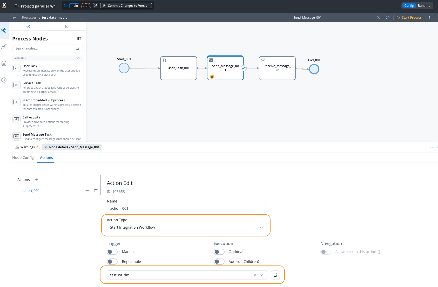
Configure Input Mapping
Access Input Mapping tab to configure the input mapping.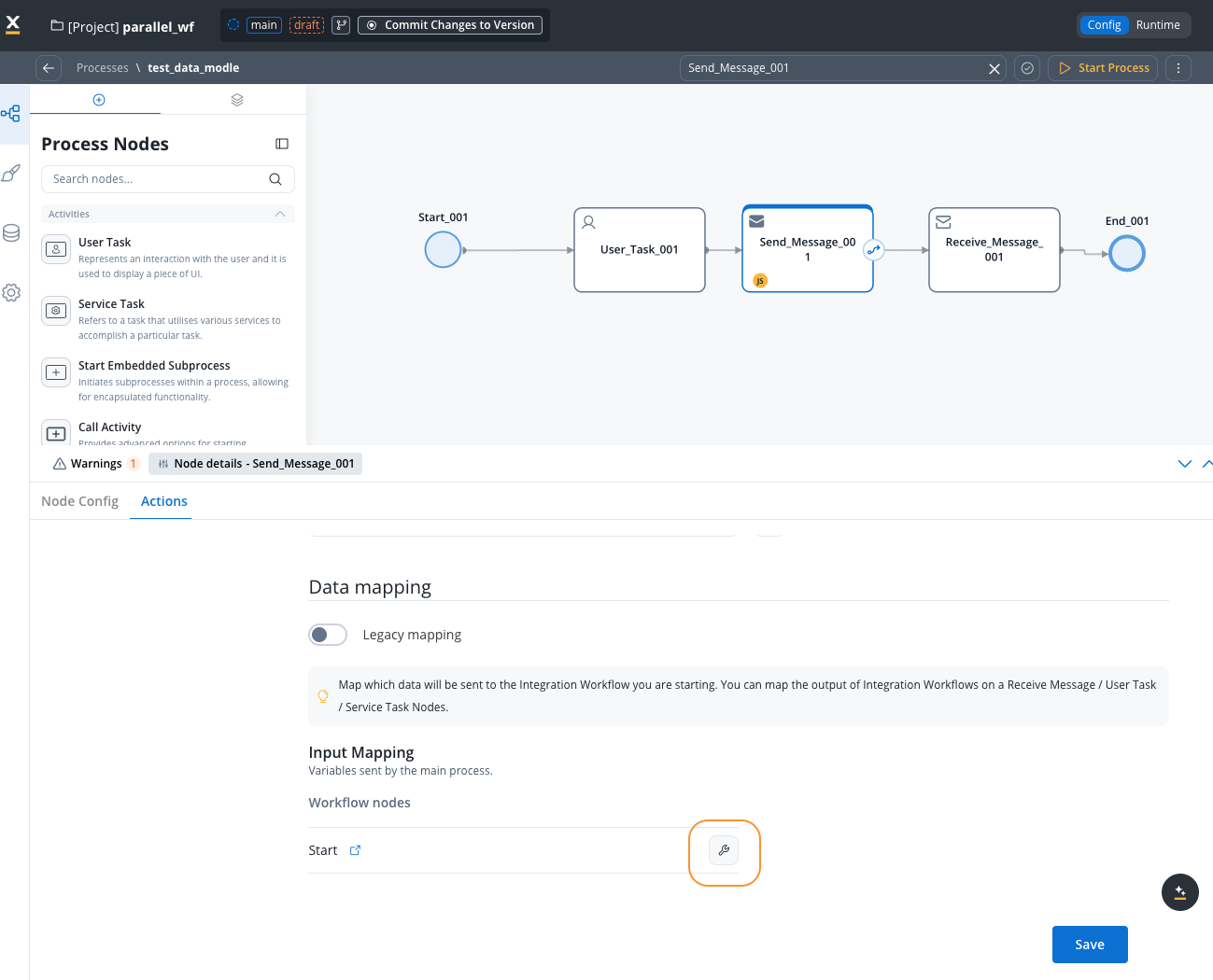 Map process data to workflow input parameters using the data mapper:
The keys on the left should match your workflow’s input parameters for consistency, though the data mapper operates independently.
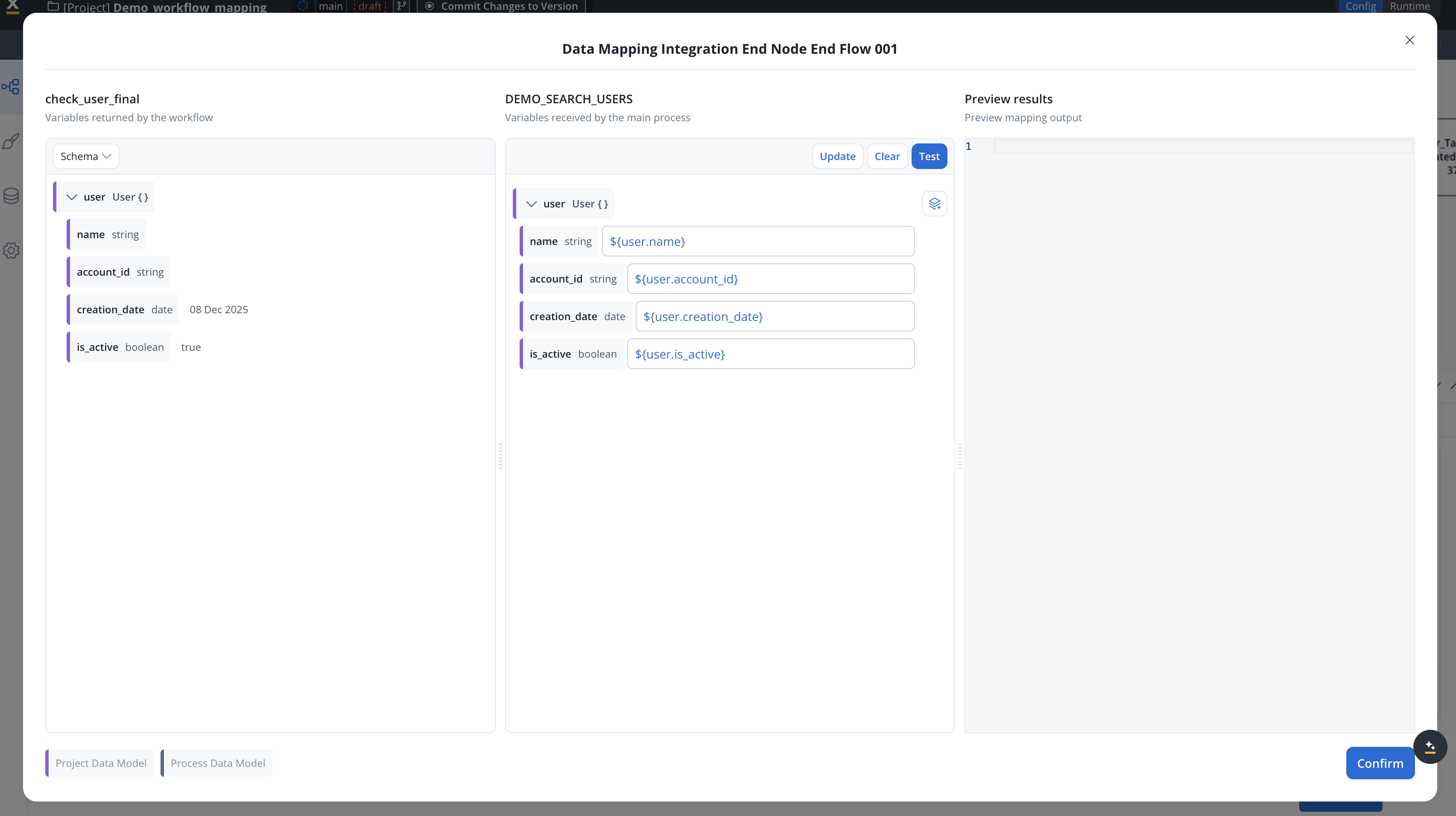
Add Receive Message Task
Add a Receive Message Task node to capture workflow output when the workflow completes.Add a Data Stream by going to the Node Config -> Integration Output -> Data Streams tab and clicking Add Data Stream.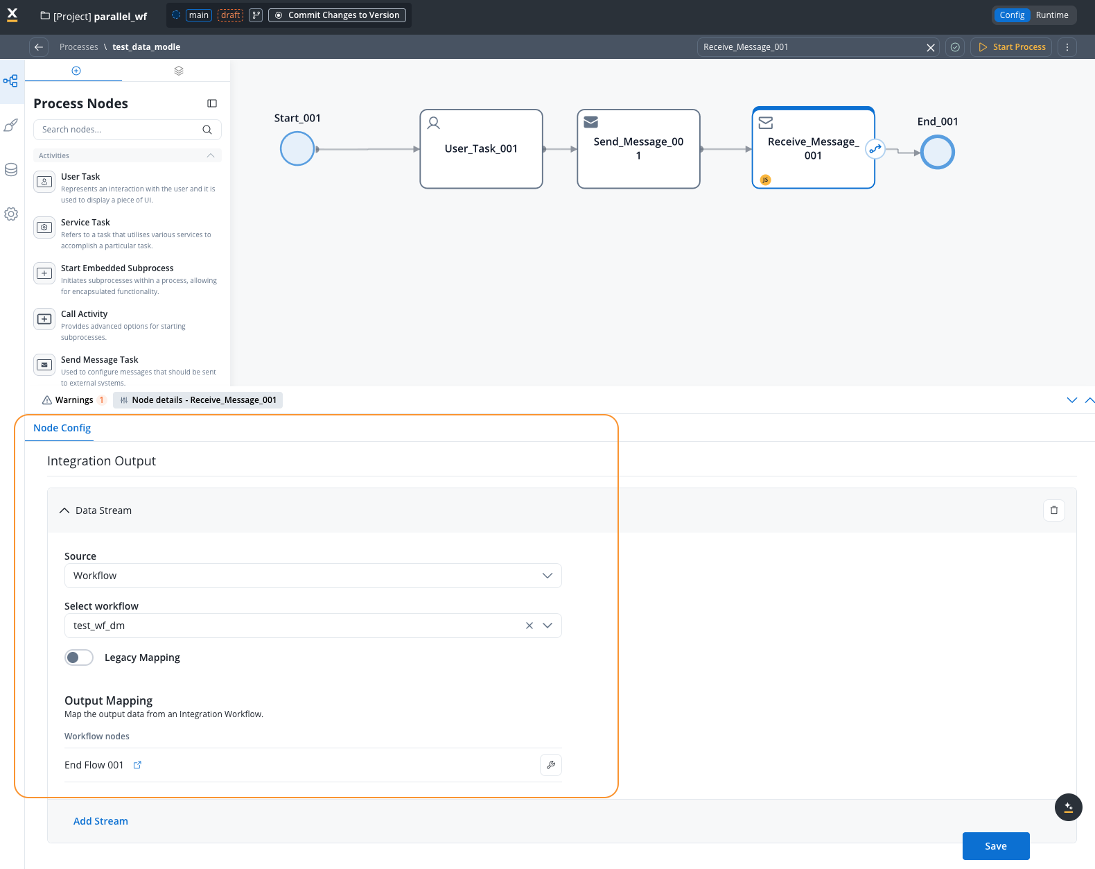
Example: User search workflow
This example demonstrates a workflow that searches for a user in the FlowX database using a username and returns the user’s available information.Workflow data model configuration
Configure your workflow data model with the following parameters: Input Parameter:username(String, required) - The user’s name to search for
user(Object) - The user object containing all available user information
Process setup
The process includes:- User Task: Contains an input field where users enter the username to search

- Search Button: Triggers the Start Integration Workflow action
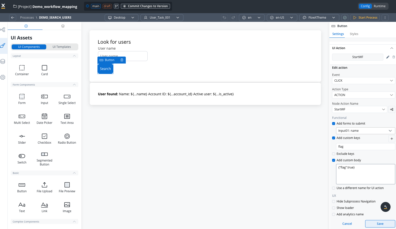
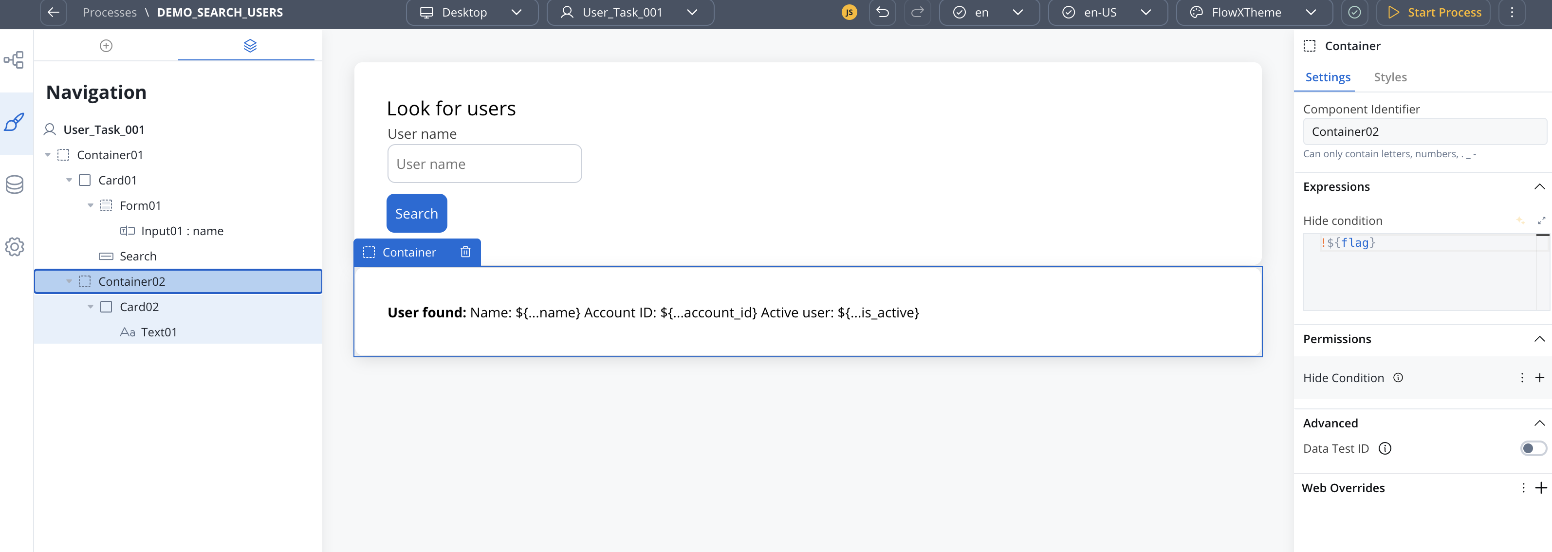
- Results Container: Configured with conditional visibility to display only when results are returned
Example
Mapping configuration
The Start Integration Workflow action requires two mapping configurations: Input Mapping (Process → Workflow): Maps the username from the main process to the workflow’s expected input variable:- Add a data stream for the workflow on the Receive Message Task
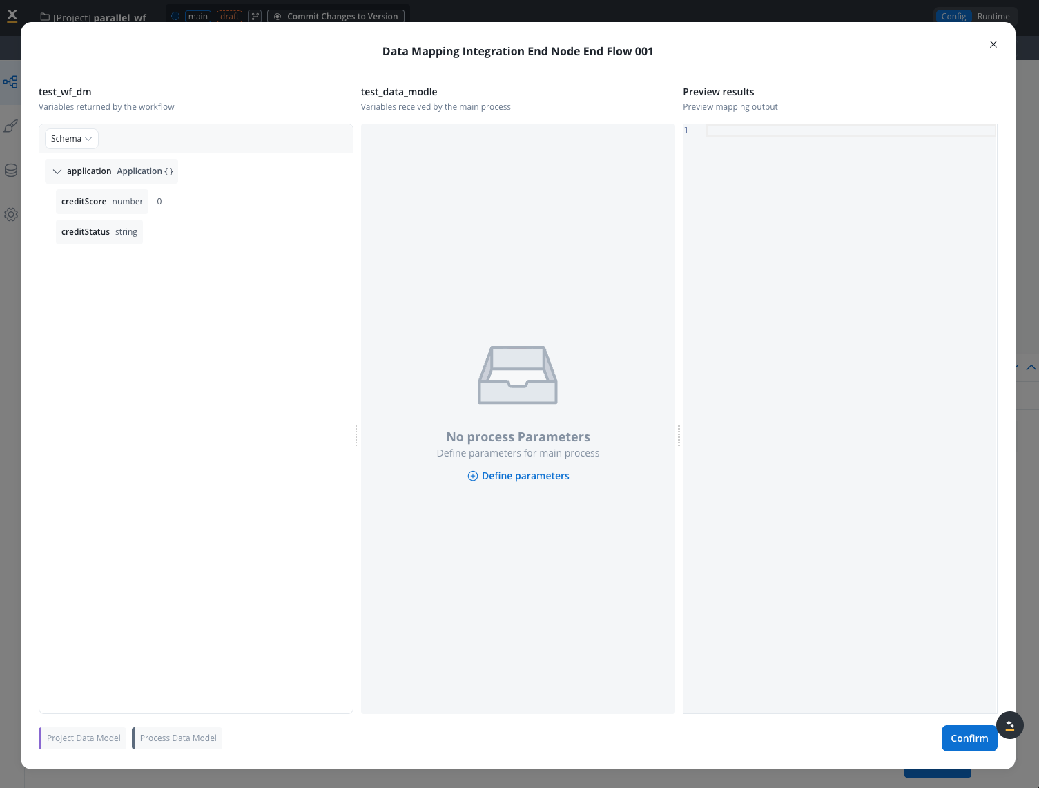
- Define the user object as the output variable needed by the main process
- Link the workflow’s returned variables to the process variables
The output mapping displays all available end nodes from the workflow. Select the appropriate end node that returns the user data.
User database
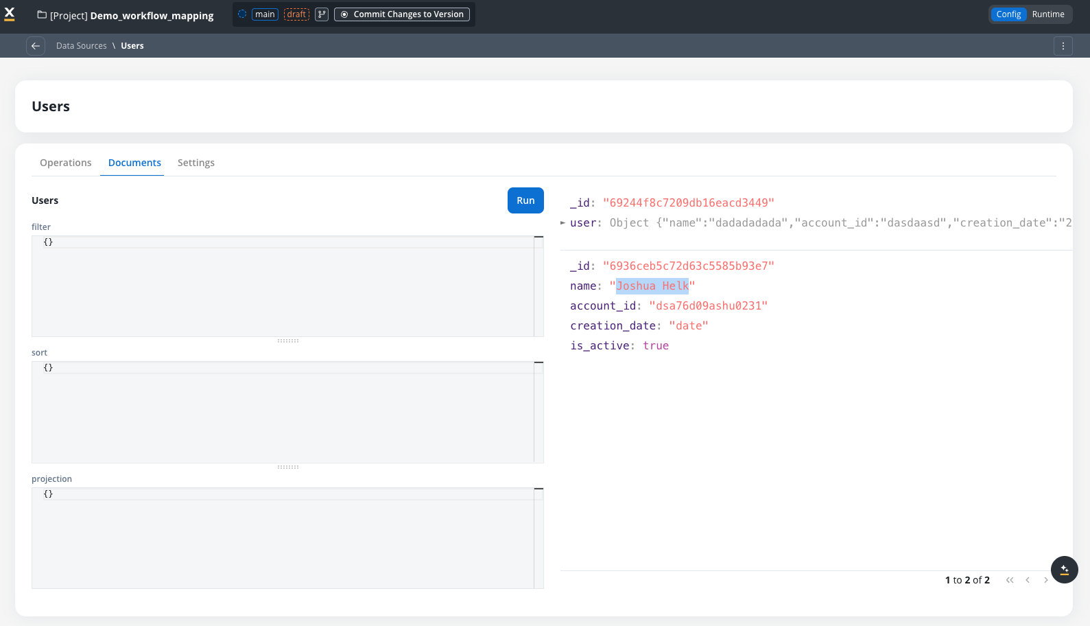
The user database is a simple database with a single user object.
Workflow diagram
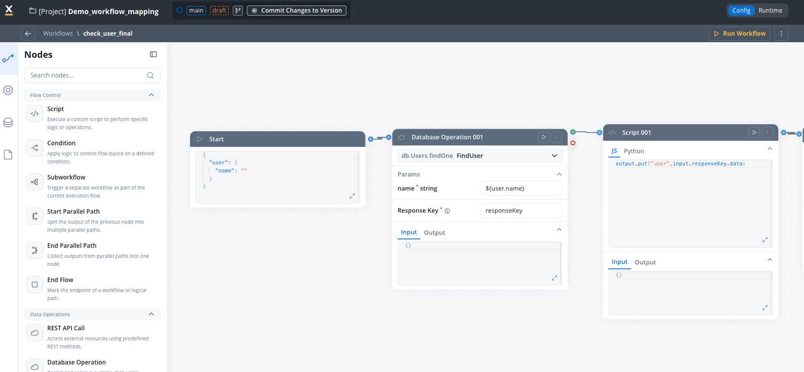
You can see the start workflow node is pre-filled with the input parameter.
Execution results
When the process runs and the search action executes: Workflow Input:Best practices
Data model structure
Use logical entities
Group related attributes into meaningful entities that represent domain concepts
Consistent naming
Use camelCase for attributes and PascalCase for entities consistently
Reuse existing data types
Reuse existing data types for bulk mapping to simplify data model creation and ensure consistency
Document everything
Add descriptions to entities and attributes for better team understanding
Keep it simple
Start with minimal data models and expand as needed
Input and output design
DO: ✅ Define only required input parameters in the input parameters✅ Use meaningful parameter names that describe the data
✅ Set appropriate data types for validation
✅ Mark parameters as required when they’re essential DON’T: ❌ Include unnecessary data in input/output parameters
❌ Use ambiguous or cryptic parameter names
❌ Make all parameters optional when some are required
❌ Change data model structure without updating mappings
Node naming
The system enforces unique node names within workflows. If you need similar operations, use descriptive suffixes:FetchCustomerData_PersonalFetchCustomerData_Financial
Limitations and compatibility
Current limitations
- Start sub-workflow node: Start sub-workflow nodes work as-is without data model integration
- Endpoint schema integration: Imported Swagger schemas are not integrated with workflow data models yet
- Database schema mapping: Database operation schemas are not mapped to workflow variables yet
Related resources
Integration Designer Overview
Learn about Integration Designer workflows and nodes
Process Data Model
Understand Process Data Models and how they work
Data Mappers
Configure data mappings between processes and workflows
Start Integration Workflow Action
Invoke workflows from process definitions
Troubleshooting
Start Node input is empty after defining input parameters
Start Node input is empty after defining input parameters
Possible causes:
- Input parameters not saved correctly
- Browser cache issues
- No input parameters defined (results in empty object)
- Save the workflow and refresh the browser
- Re-open the workflow diagram tab
- Check that the input parameters contains attributes
- Verify attributes are marked as required if needed
- If no input parameters are defined, the Start Node will contain an empty object
{}
Manual changes to Start Node JSON are lost
Manual changes to Start Node JSON are lost
Problem: You manually edited the JSON in the Start Node, but your changes disappeared after refreshing or reopening the workflow.Cause:
The Start Node is automatically populated from the input parameters definition. Any manual edits are overwritten when the workflow diagram is refreshed or reopened.Solution:
- Update the input parameters definition in the Input/Output Parameters tab instead of editing the Start Node JSON directly
- Changes to the input parameters will automatically reflect in the Start Node
- If you need a different structure, modify the data model and input parameters accordingly
Node name uniqueness validation error
Node name uniqueness validation error
Error message: “Node name must be unique within the workflow”Solution:
- Choose a different, more descriptive node name
- The system will suggest appending an index (e.g.,
_2) - Use descriptive suffixes instead (e.g.,
_Personal,_Financial)
Data mapper not working after adding data model
Data mapper not working after adding data model
Possible causes:
- Input parameters keys don’t match process data mapper
- Data types mismatch
- Ensure data mapper keys match input parameters attribute names exactly
- Verify data types are compatible (string to string, number to number)
- Check for typos in attribute names
- Review process data model to workflow data model mapping
Cannot delete entity or attribute
Cannot delete entity or attribute
Error message: “Entity/Attribute is referenced and cannot be deleted”Solution:
- Check attribute usages using the API:
GET .../attributes/{name}/usages - Remove references from input/output parameters first
- Update workflow nodes that use the attribute
- Then retry deletion