Integration Designer
The Integration Designer simplifies the integration of FlowX with external systems using REST APIs. It offers a user-friendly graphical interface with intuitive drag-and-drop functionality for defining data models, orchestrating workflows, and configuring system endpoints.
Did you know?
Overview
Integration Designer facilitates the integration of the FlowX platform with external systems, applications, and data sources.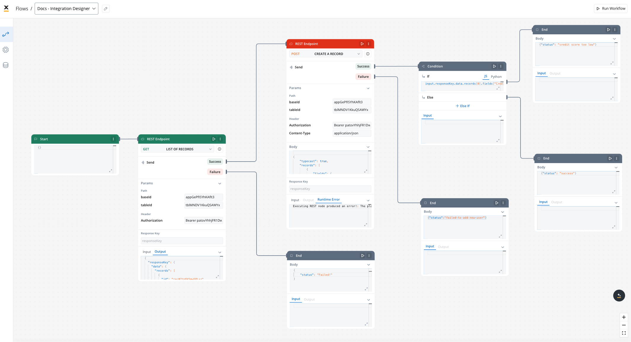
Key features
Drag-and-Drop Simplicity
Visual REST API Integration
Real-Time Testing and Validation
Managing integration endpoints
Systems
A system is a collection of resources—endpoints, authentication, and variables—used to define and run integration workflows.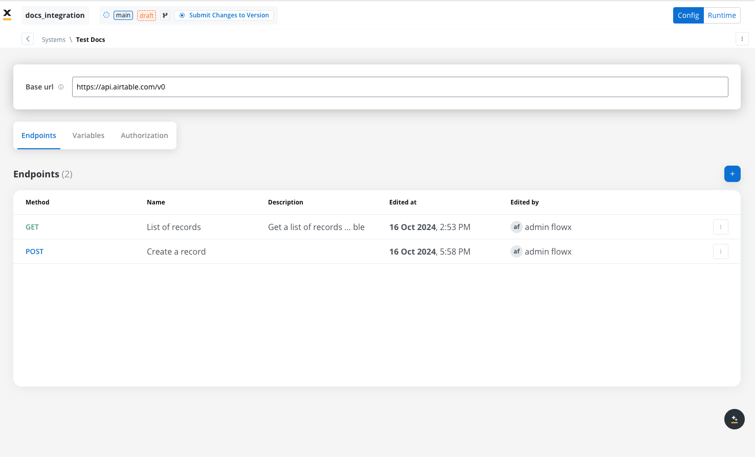
Creating a new system definition
With Systems feature you can create, update, and organize endpoints used in API integrations. These endpoints are integral to building workflows within the Integration Designer, offering flexibility and ease of use for managing connections between systems. Endpoints can be configured, tested, and reused across multiple workflows, streamlining the integration process.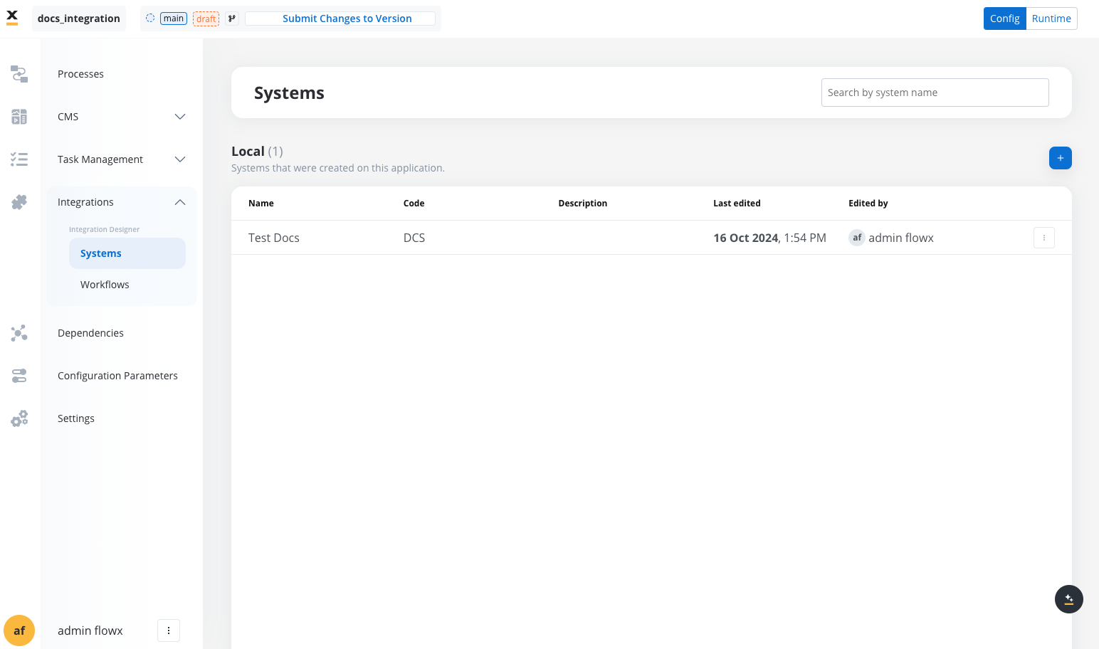
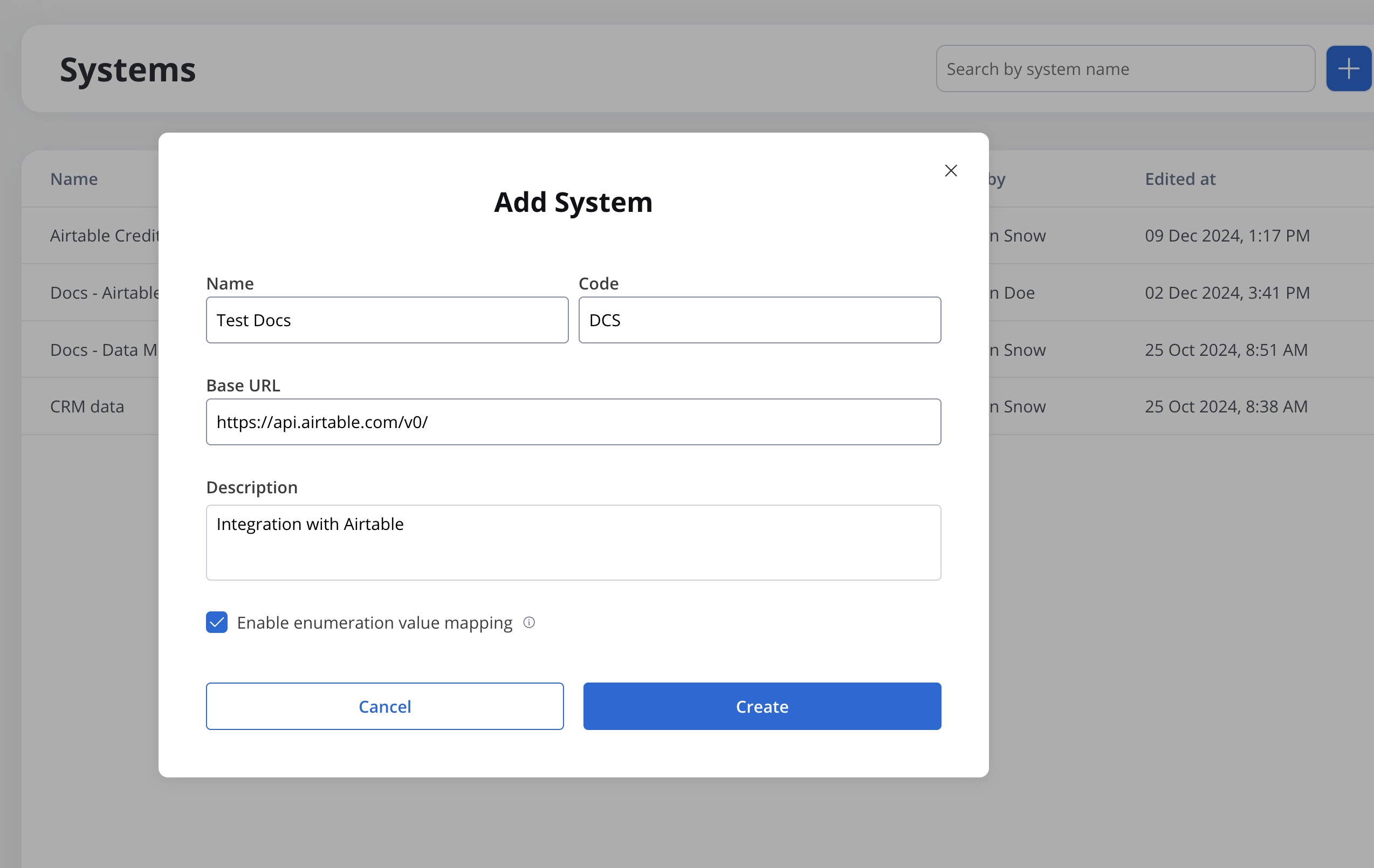
- Add a New System, set the system’s unique code, name, and description:
- Name: The system’s name.
- Code: A unique identifier for the external system.
- Base URL: The base URL is the main address of a website or web application, typically consisting of the protocol (
httporhttps), domain name, and a path. - Description: A description of the system and its purpose.
- Enable enumeration value mapping: If checked, this system will be listed under the mapped enumerations. See enumerations section for more details.
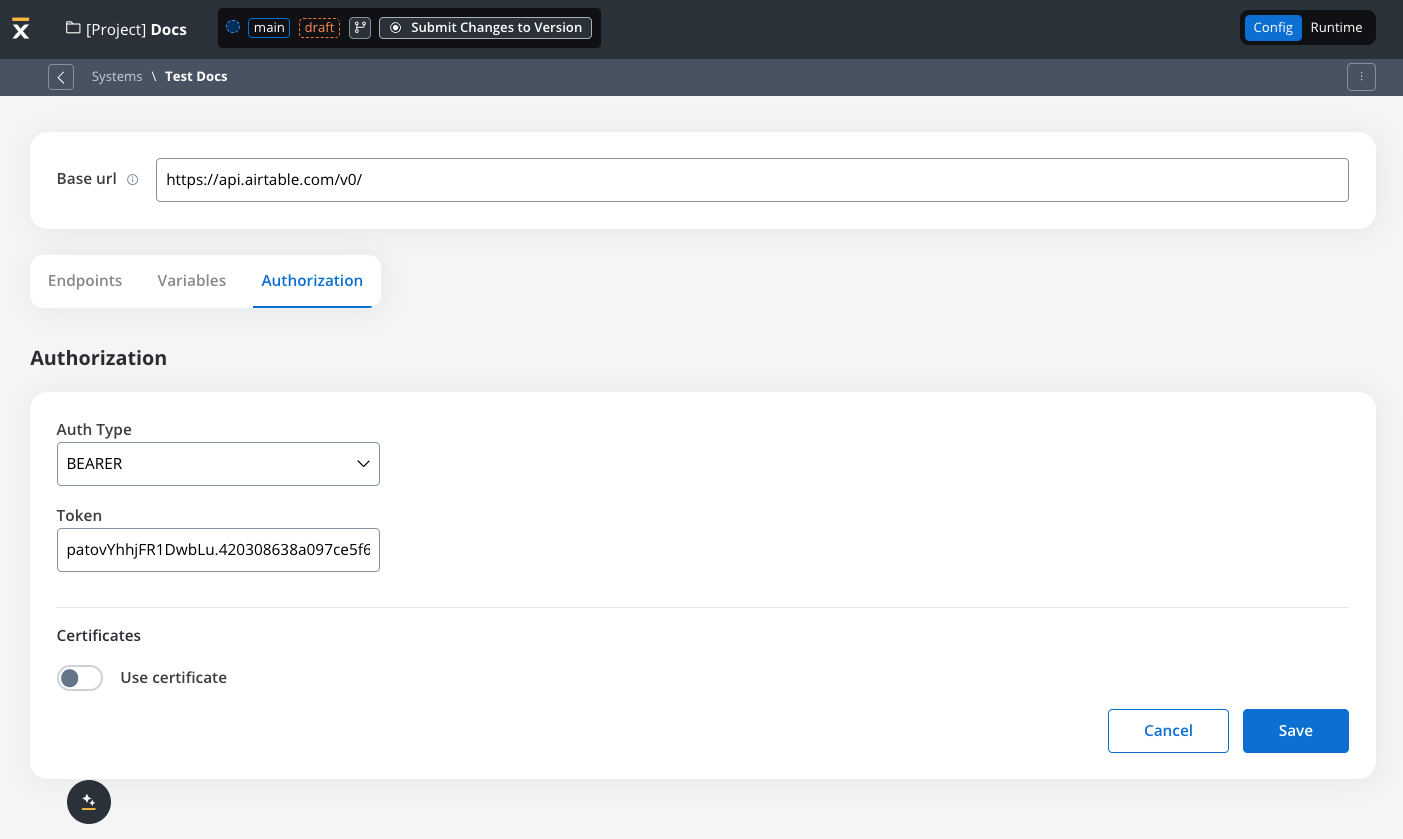
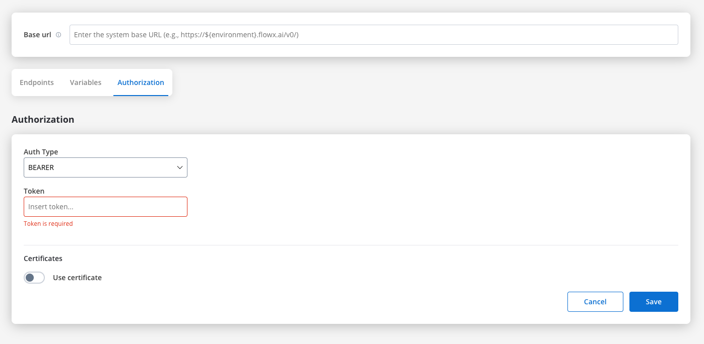
https://api.${environment}.example.com/v1.Additionally, keep in mind that the priority for determining the configuration parameter (e.g., base URL) follows this order: first, input from the user/process; second, configuration parameters overrides (set directly on FlowX.AI designer or environment variables); and lastly, configuration parameters.- Set up authorization (Service Token, Bearer Token, or No Auth). In our example, we will set the auth type as a bearer and we will set it at system level:
Defining REST integration endpoints
In this section you can define REST API endpoints that can be reused across different workflows.- Under the Endpoints section, add the necessary endpoints for system integration.
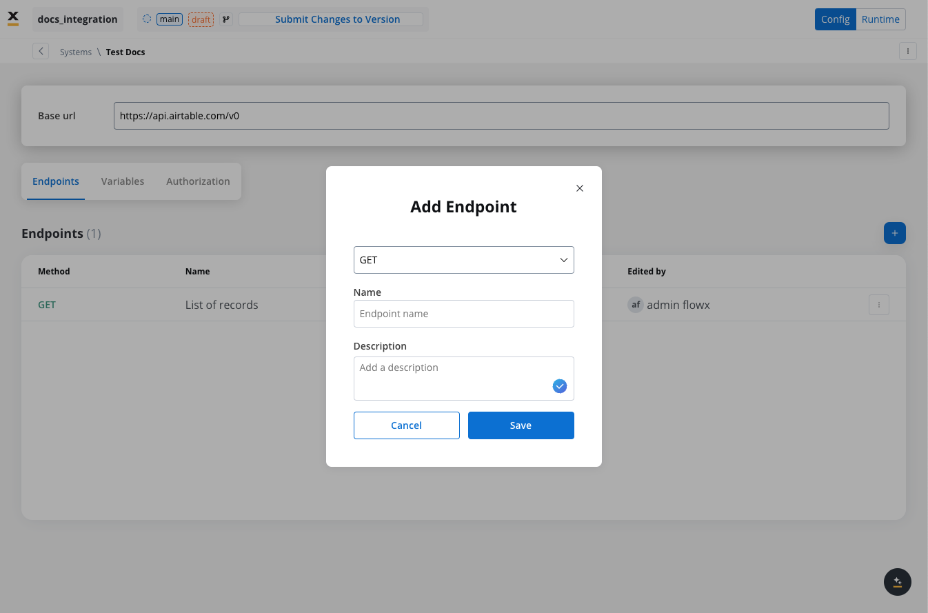
- Configure an endpoint by filling in the following properties:
- Method: GET, POST, PUT, PATCH, DELETE.
- Path: Path for the endpoint.
- Parameters: Path, query, and header parameters.
- Response Settings: Expected response codes and formats.
- Body: JSON payload for requests.
Defining variables
The Variables tab allows you to store system-specific variables that can be referenced throughout workflows using the format${variableName}.
These declared variables can be utilized not only in workflows but also in other sections, such as the Endpoint or Authorization tabs.
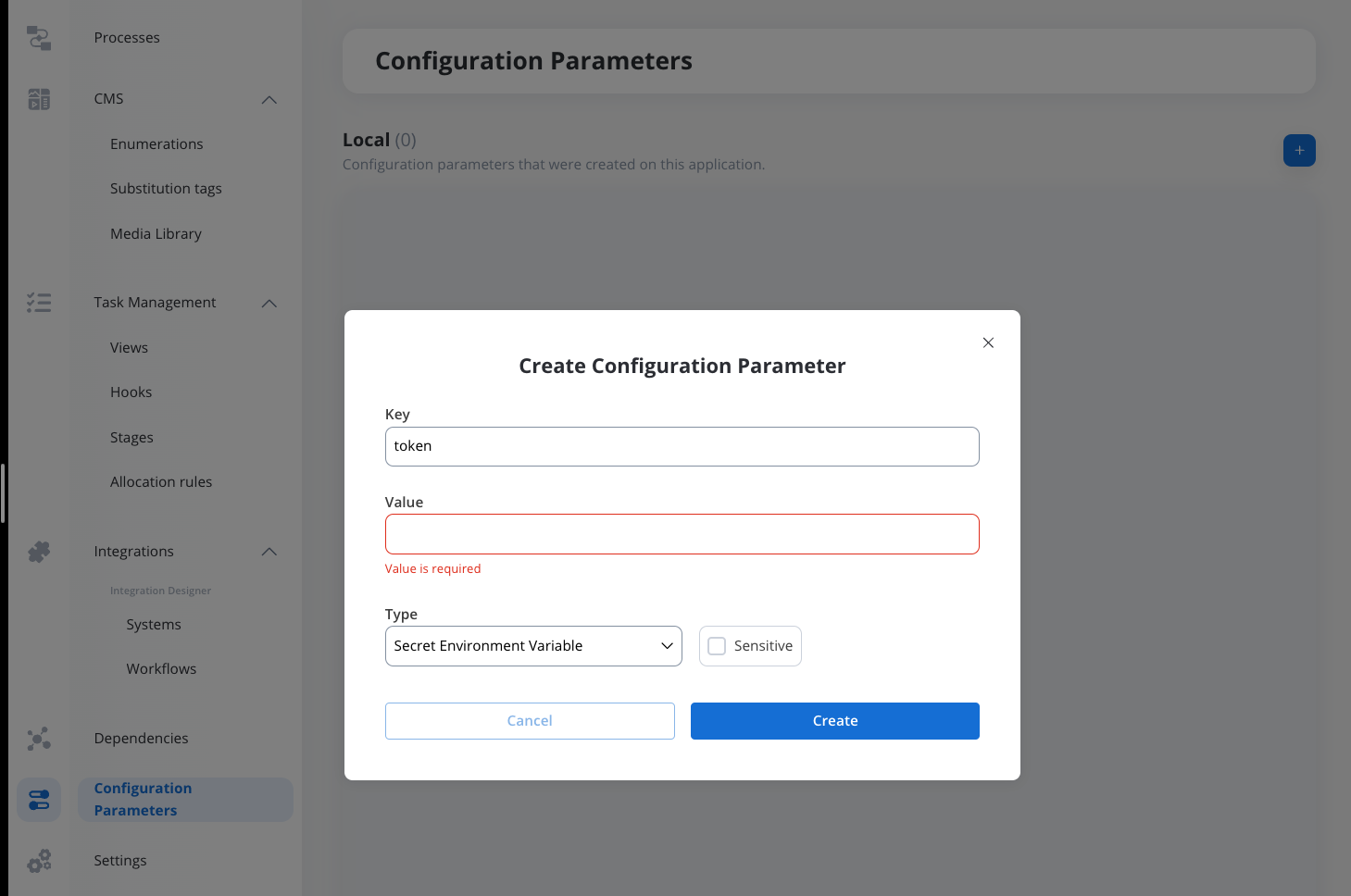
- For our integration example, you can declare configuration parameters and use the variables to store your tableId and baseId and reference them the Variables tab.
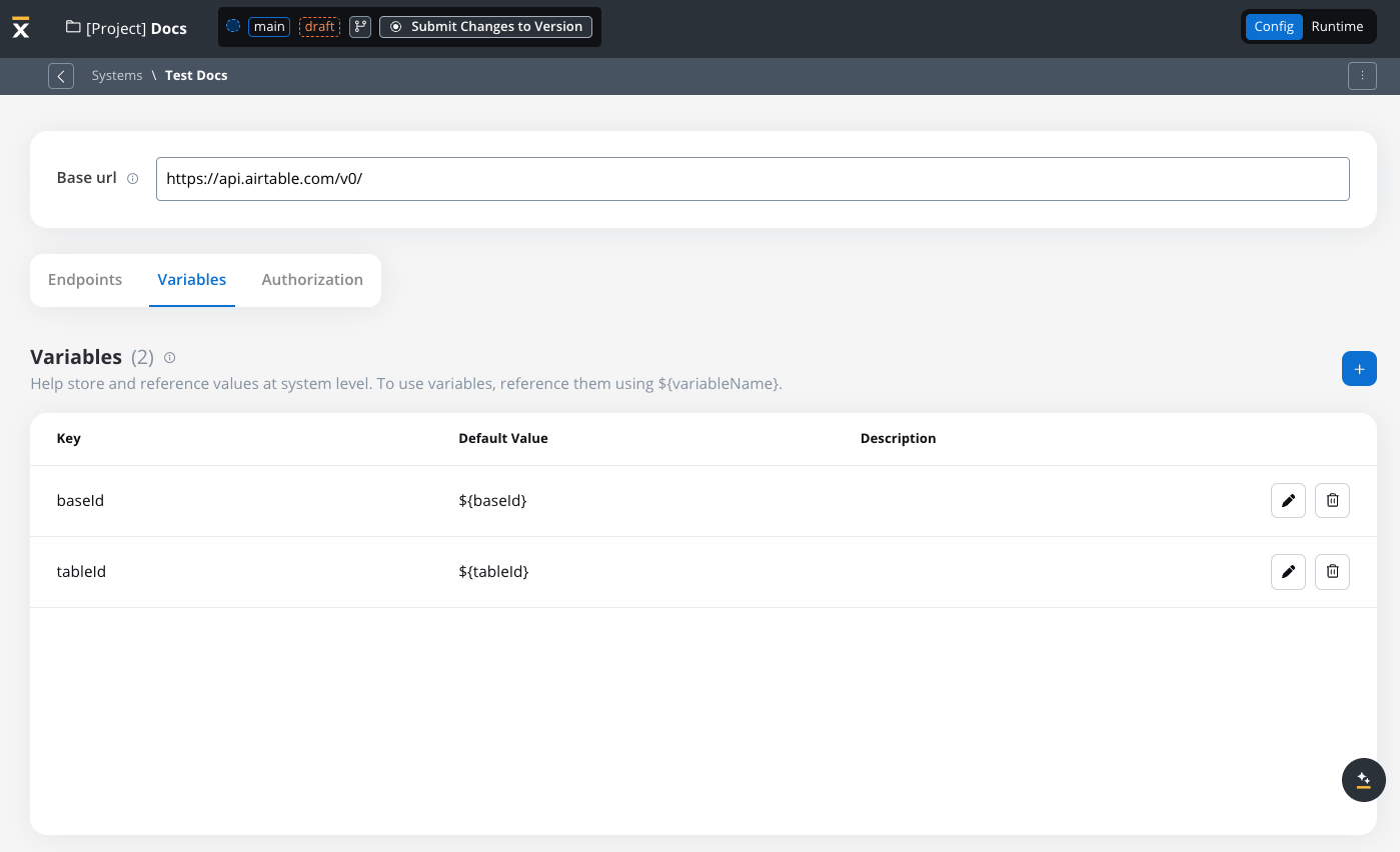
- Use variables in the Base URL to switch between different environments, such as UAT or production.
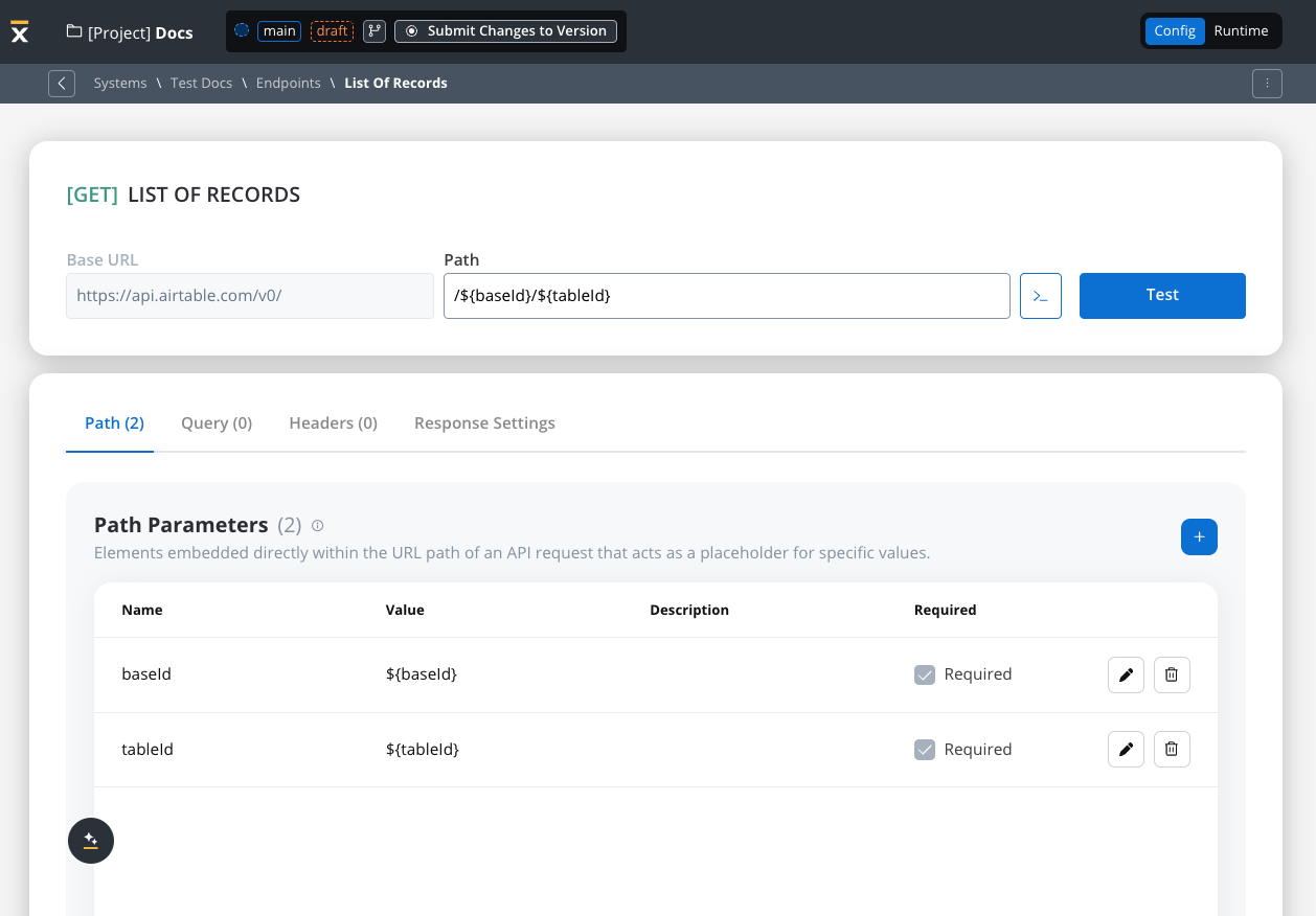
Endpoint parameter types
When configuring endpoints, several parameter types help define how the endpoint interacts with external systems. These parameters ensure that requests are properly formatted and data is correctly passed.Path parameters
Elements embedded directly within the URL path of an API request that acts as a placeholder for specific value.- Used to specify variable parts of the endpoint URL (e.g.,
/users/{userId}). - Defined with
${parameter}format. - Mandatory in the request URL.
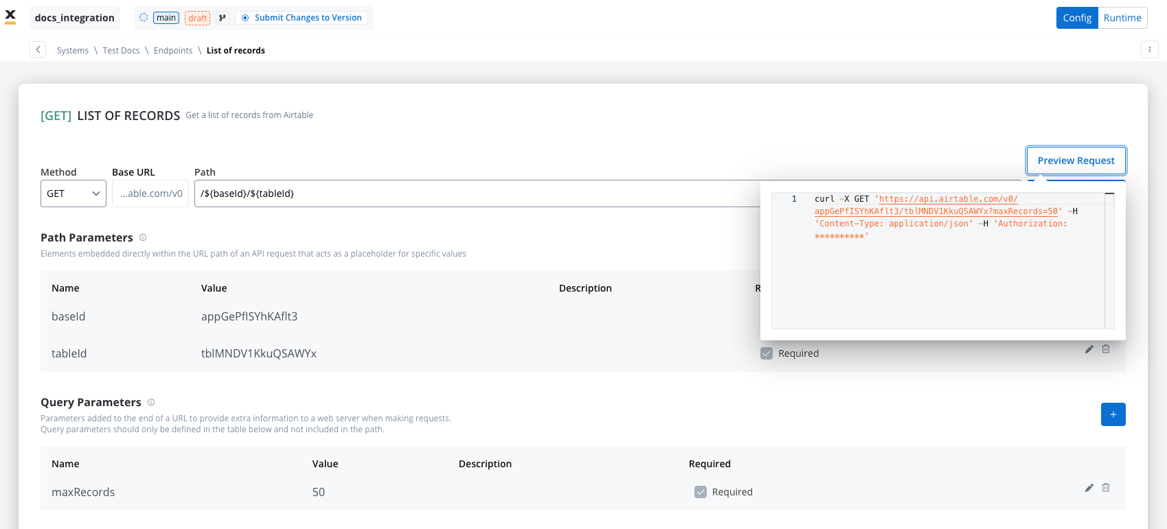
Query parameters
Query parameters are added to the end of a URL to provide extra information to a web server when making requests.- Query parameters are appended to the URL after a
?symbol and are typically used for filtering or pagination (e.g.,?search=value) - Useful for filtering or pagination.
- Example URL with query parameters: https://api.example.com/users?search=johndoe&page=2.
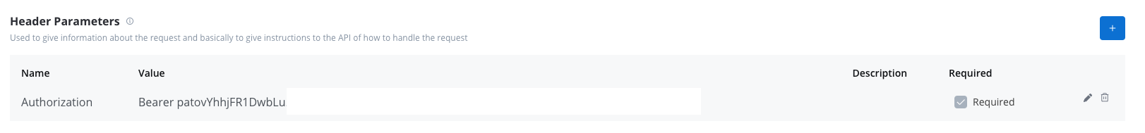
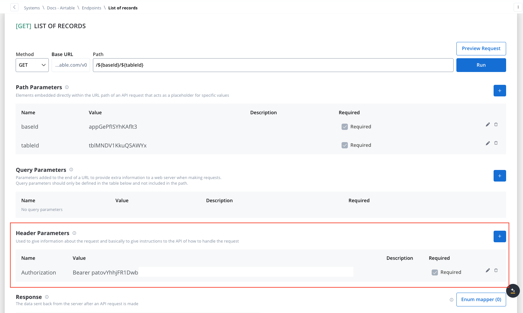
Header parameters
Used to give information about the request and basically to give instructions to the API of how to handle the request- Header parameters (HTTP headers) provide extra details about the request or its message body.
- They are not part of the URL. Default values can be set for testing and overridden in the workflow.
- Custom headers sent with the request (e.g.,
Authorization: Bearer token). - Define metadata or authorization details.
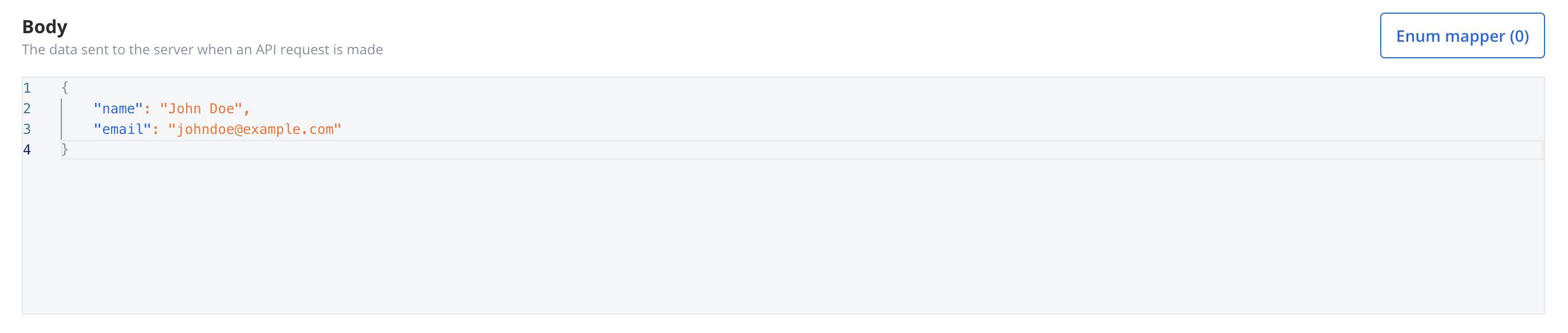
Body parameters
The data sent to the server when an API request is made.- These are the data fields included in the body of a request, usually in JSON format.
- Body parameters are used in POST, PUT, and PATCH requests to send data to the external system (e.g., creating or updating a resource).
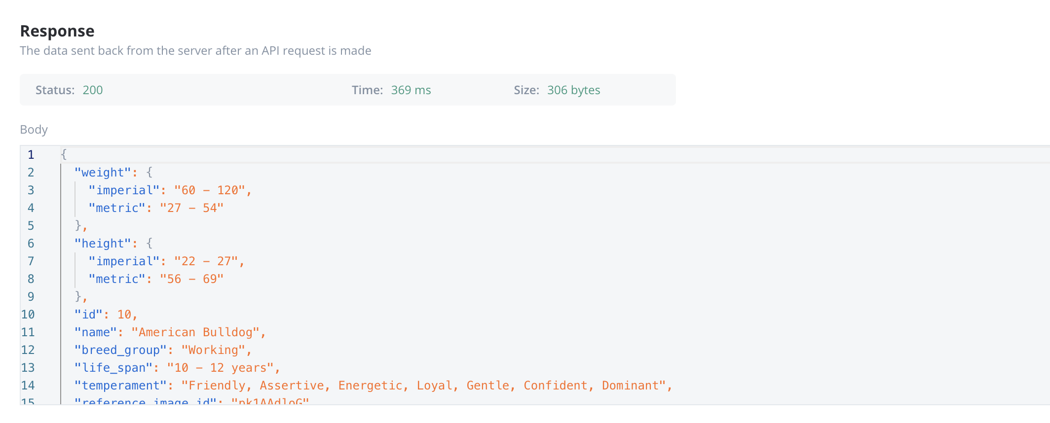
Response body parameters
The data sent back from the server after an API request is made.- These parameters are part of the response returned by the external system after a request is processed. They contain the data that the system sends back.
- Typically returned in GET, POST, PUT, and PATCH requests. Response body parameters provide details about the result of the request (e.g., confirmation of resource creation, or data retrieval)
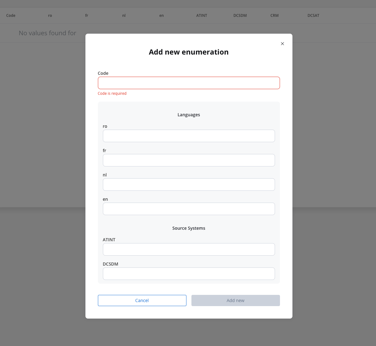
Enum mapper
The enum mapper for the request body enables you to configure enumerations for specific keys in the request body, aligning them with values from the External System or translations into another language.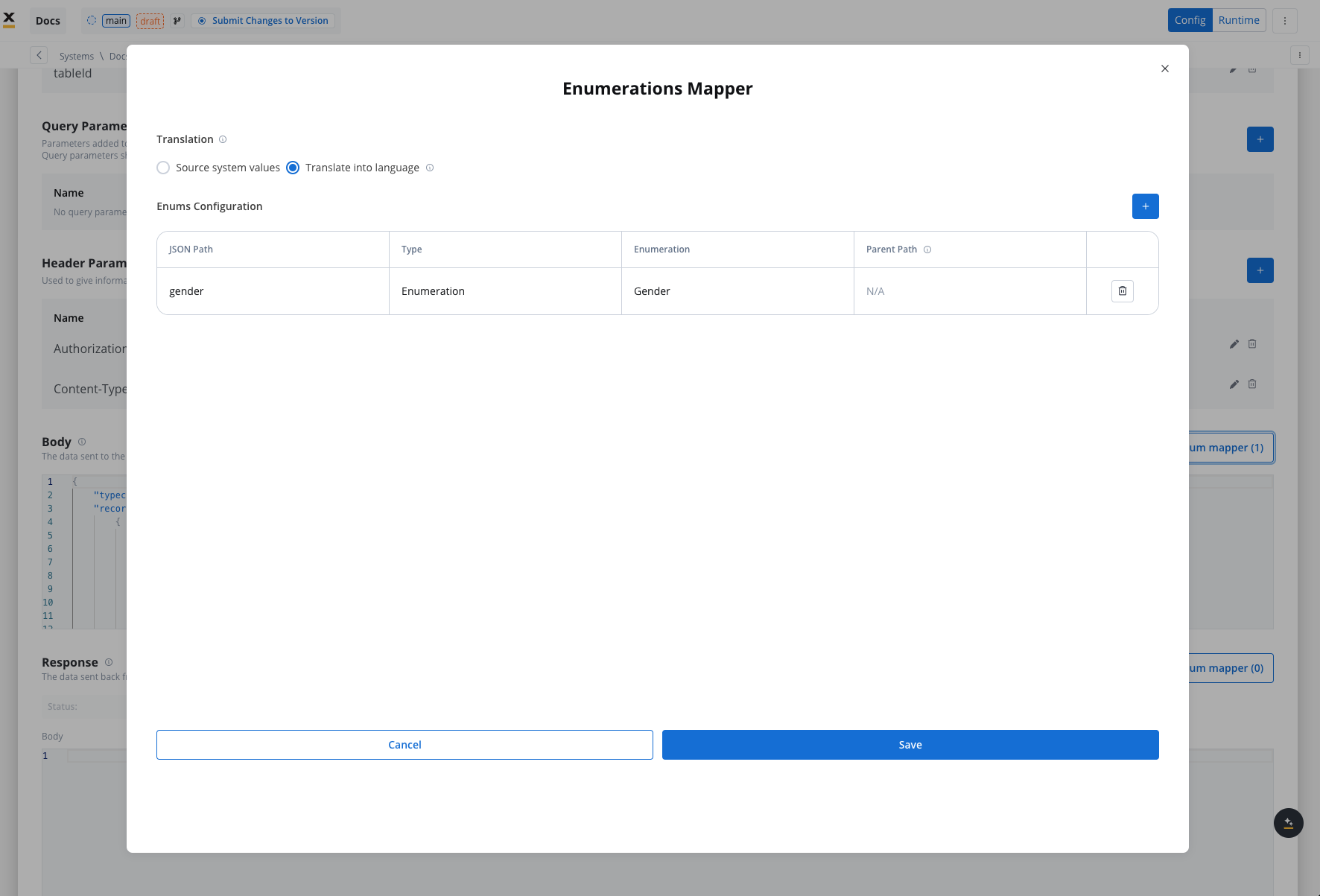
Configuring authorization
- Select the required Authorization Type from a predefined list.
- Enter the relevant details based on the selected type (e.g., Realm and Client ID for Service Accounts).
- These details will be automatically included in the request headers when the integration is executed.
Authorization methods
The Integration Designer supports several authorization methods, allowing you to configure the security settings for API calls. Depending on the external system’s requirements, you can choose one of the following authorization formats: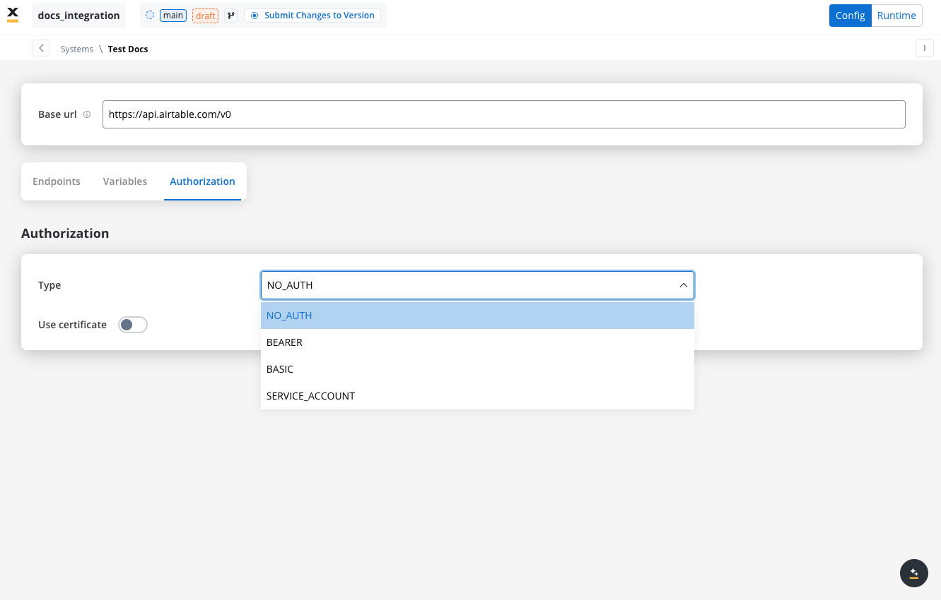
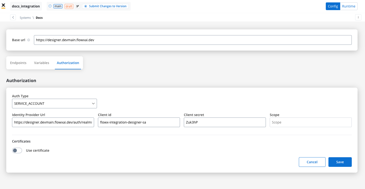
Service account
Service Account authentication requires the following key fields:- Identity Provider Url: The URL for the identity provider responsible for authenticating the service account.
- Client Id: The unique identifier for the client within the realm.
- Client secret: A secure secret used to authenticate the client alongside the Client ID.
- Scope: Specifies the access level or permissions for the service account.
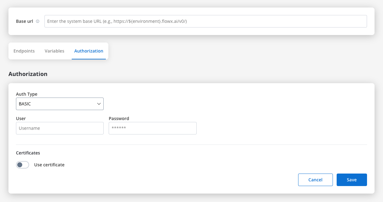
Basic authentication
- Requires the following credentials:
- Username: The account’s username.
- Password: The account’s password.
- Suitable for systems that rely on simple username/password combinations for access.
Bearer
- Requires an Access Token to be included in the request headers.
- Commonly used for OAuth 2.0 implementations.
- Header Configuration: Use the format
Authorization: Bearer {access_token}in headers of requests needing authentication.
- System-Level Example: You can store the Bearer token at the system level, as shown in the example below, ensuring it’s applied automatically to future API calls:
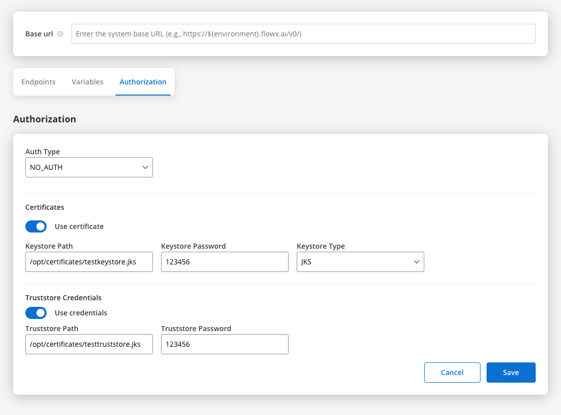
Certificates
You might want to access another external system that require a certificate to do that. Use this setup to configure the secure communication with the system. It includes paths to both a Keystore (which holds the client certificate) and a Truststore (which holds trusted certificates). You can toggle these features based on the security requirements of the integration.
- Keystore Path: Specifies the file path to the keystore, in this case,
/opt/certificates/testkeystore.jks. The keystore contains the client certificate used for securing the connection. - Keystore Password: The password used to unlock the keystore.
- Keystore Type: The format of the keystore, JKS or PKCS12, depending on the system requirements.
- Truststore Path: The file path is set to
/opt/certificates/testtruststore.jks, specifying the location of the truststore that holds trusted certificates. - Truststore Password: Password to access the truststore.
Workflows
A workflow defines a series of tasks and processes to automate system integrations. Within the Integration Designer, workflows can be configured using different components to ensure efficient data exchange and process orchestration.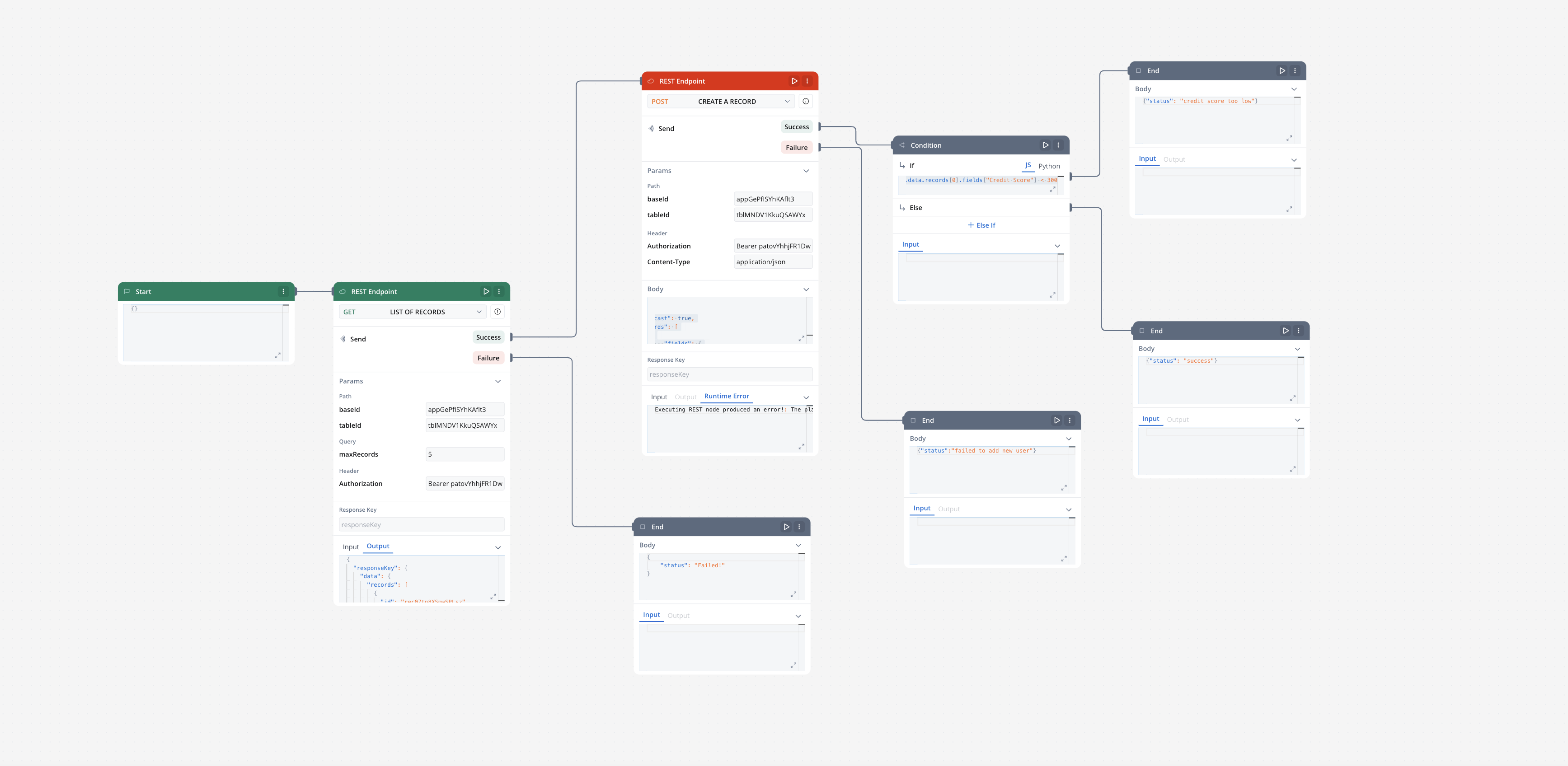
Creating a workflow
- Navigate to Workflow Designer:
- In FlowX.AI Designer to Projects -> Your application -> Integrations -> Workflows.
- Create a New Workflow, provide a name and description, and save it.
- Start to design your workflow by adding nodes to represent the steps of your workflow:
- Start Node: Defines where the workflow begins and also defines the input parameter for subsequent nodes.
- REST endpoint nodes: Add REST API calls for fetching or sending data.
- Fork nodes (conditions): Add conditional logic for decision-making.
- Data mapping nodes (scripts): Write custom scripts in JavaScript or Python.
- End Nodes: Capture output data as the completed workflow result, ensuring the process concludes with all required information.

Workflow Nodes Overview
| Node Type | Purpose |
|---|---|
| Start Node | Defines workflow input and initializes data |
| REST Endpoint Node | Makes REST API calls to external systems |
| FlowX Database Node | Reads/writes data to the FlowX Database |
| Condition (Fork) | Adds conditional logic and parallel branches |
| Script Node | Transforms or maps data using JavaScript or Python |
| Subworkflow Node | Invokes another workflow as a modular, reusable subcomponent |
| End Node | Captures and outputs the final result of the workflow |
Start Node
The Start node is the mandatory first node in any workflow. It defines the input data model and passes this data to subsequent nodes.REST Endpoint Node
Enables communication with external systems via REST API calls. Supports GET, POST, PUT, PATCH, and DELETE methods. Endpoints are selected from a dropdown, grouped by system.- Params: Configure path, query, and header parameters.
- Input/Output: Input is auto-populated from the previous node; output displays the API response.
FlowX Database Node
Allows you to read and write data to the FlowX Database within your workflow.Condition (Fork) Node
Evaluates logical conditions (JavaScript or Python) to direct workflow execution along different branches.- If/Else: Routes based on condition evaluation.
- Parallel Processing: Supports multiple branches for concurrent execution.
Script Node
Executes custom JavaScript or Python code to transform, map, or enrich data between nodes.Subworkflow Node
The Subworkflow node allows you to modularize complex workflows by invoking other workflows as reusable subcomponents. This approach streamlines process design, promotes reuse, and simplifies maintenance.Add a Subworkflow Node
Configure the Subworkflow Node
- Workflow Selection: Pick the workflow to invoke.
- Open: Edit the subworkflow in a new tab.
- Preview: View the workflow canvas in a popup.
- Response Key: Set a key (e.g.,
response_key) for output. - Input: Provide input in JSON format.
- Output: Output is read-only JSON after execution.
Execution logic and error handling
- Parent workflow waits for subworkflow completion before proceeding.
- If the subworkflow fails, the parent workflow halts at this node.
- Subworkflow output is available to downstream nodes via the response key.
- Logs include workflow name, instance ID, and node statuses for both parent and subworkflow.
[name] subworkflow not found.Console logging, navigation, and read-only mode
- Console shows input/output, workflow name, and instance ID for each subworkflow run.
- Open subworkflow in a new tab for debugging from the console.
- Breadcrumbs enable navigation between parent and subworkflow details.
- In committed/upper environments, subworkflow configuration is read-only and node runs are disabled (preview/open only).
Use case: CRM Data Retrieval with Subworkflows
Suppose you need to retrieve CRM details in a subworkflow and use the output for further actions in the parent workflow.Create the Subworkflow
Add a Subworkflow Node in the Parent Workflow
Use Subworkflow Output in Parent Workflow
responseKey.Monitor and Debug
End Node
The End node signifies the termination of a workflow’s execution. It collects the final output and completes the workflow process.- Receives input in JSON format from the previous node.
- Output represents the final data model of the workflow.
- Multiple End nodes are allowed for different execution paths.
Integration with external systems
This example demonstrates how to integrate FlowX with an external system, in this example, using Airtable, to manage and update user credit status data. It walks through the setup of an integration system, defining API endpoints, creating workflows, and linking them to BPMN processes in FlowX Designer.Integration in FlowX
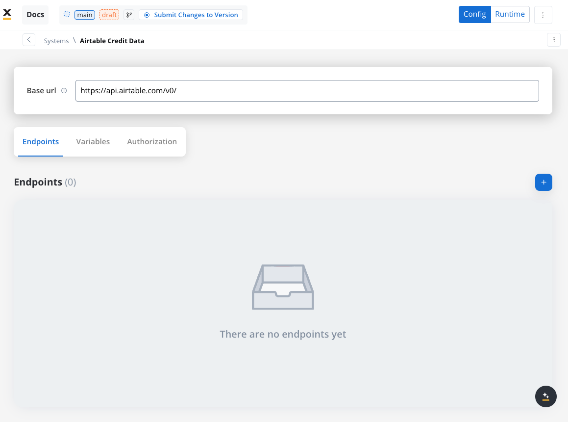
Define a System
- Name: Airtable Credit Data
- Base URL:
https://api.airtable.com/v0/
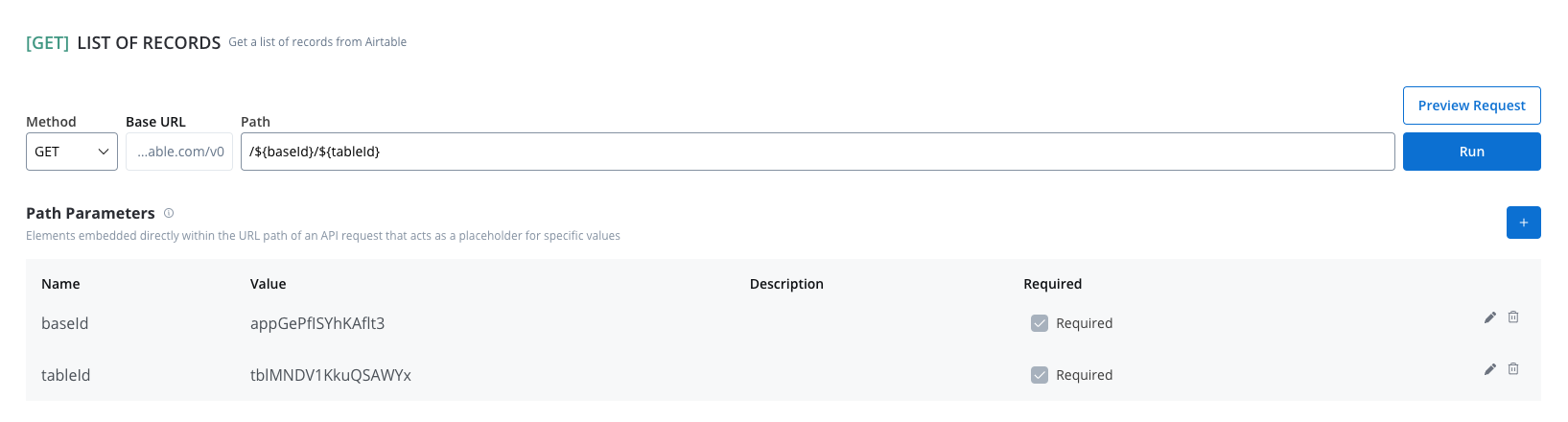
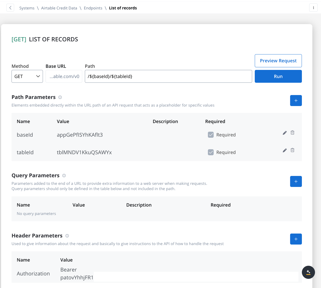
Define Endpoints
- Get Records Endpoint:
- Method: GET
- Path:
/${baseId}/${tableId} - Path Parameters: Add the values for the baseId and for the tableId so they will be available in the path.
- Header Parameters: Authorization Bearer token
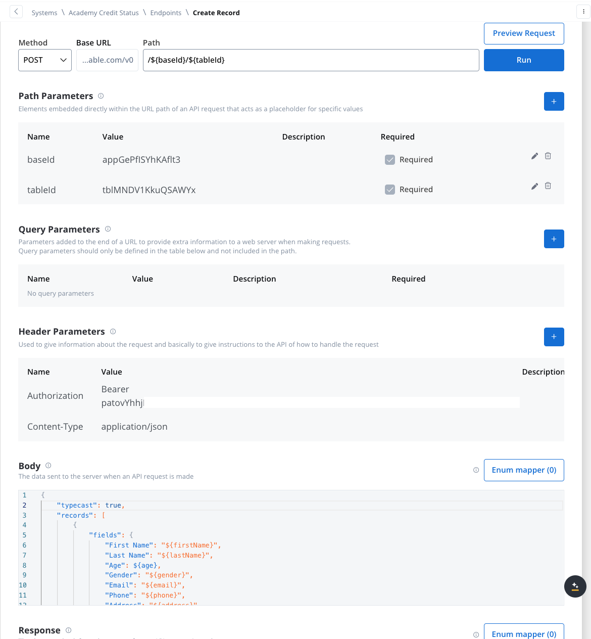
- Create Records Endpoint:
- Method: POST
- Path:
/${baseId}/${tableId} - Path Parameters: Add the values for the baseId and for the tableId so they will be available in the path.
- Header Parameters:
Content-Type: application/json- Authorization Bearer token
- Body: JSON format containing the fields for the new record. Example:
Design the Workflow
- Open the Workflow Designer and create a new workflow.
- Provide a name and description.
- Configure Workflow Nodes:
- Start Node: Initialize the workflow.

- REST Node: Set up API calls:
- GET Endpoint for fetching records from Airtable.
- POST Endpoint for creating new records.
- Condition Node: Add logic to handle credit scores (e.g., triggering a warning if the credit score is below 300).
- Script Node: Include custom scripts if needed for processing data (not used in this example).
- End Node: Define the end of the workflow with success or failure outcomes.
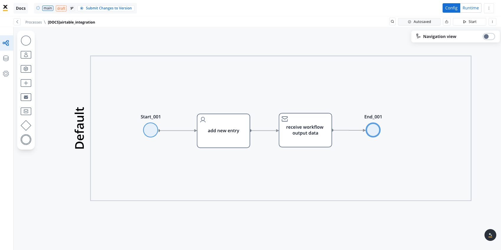
Link the Workflow to a Process
- Integrate the workflow into a BPMN process:
- Open the process diagram and include a User Task and a Receive Message Task.
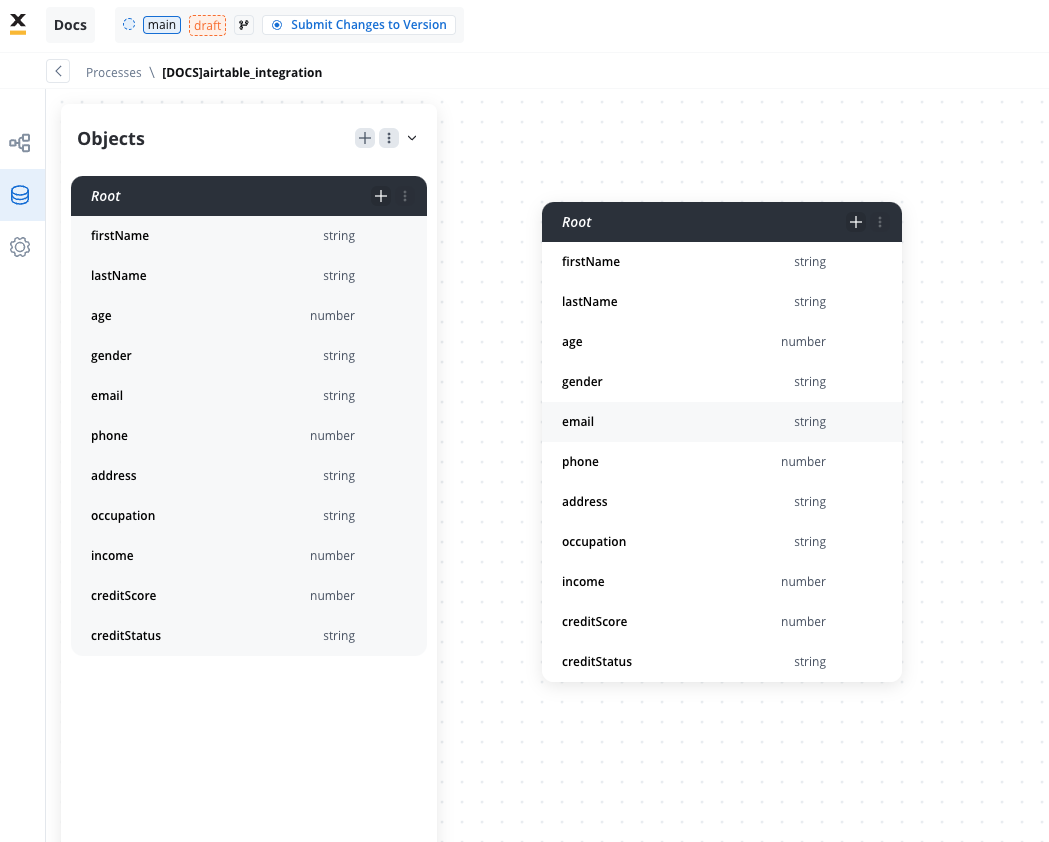
- Map Data in the UI Designer:
- Create the data model
- Link data attributes from the data model to form fields, ensuring the user input aligns with the expected parameters.
- Add a Start Integration Workflow node action:
- Make sure all the input will be captured.
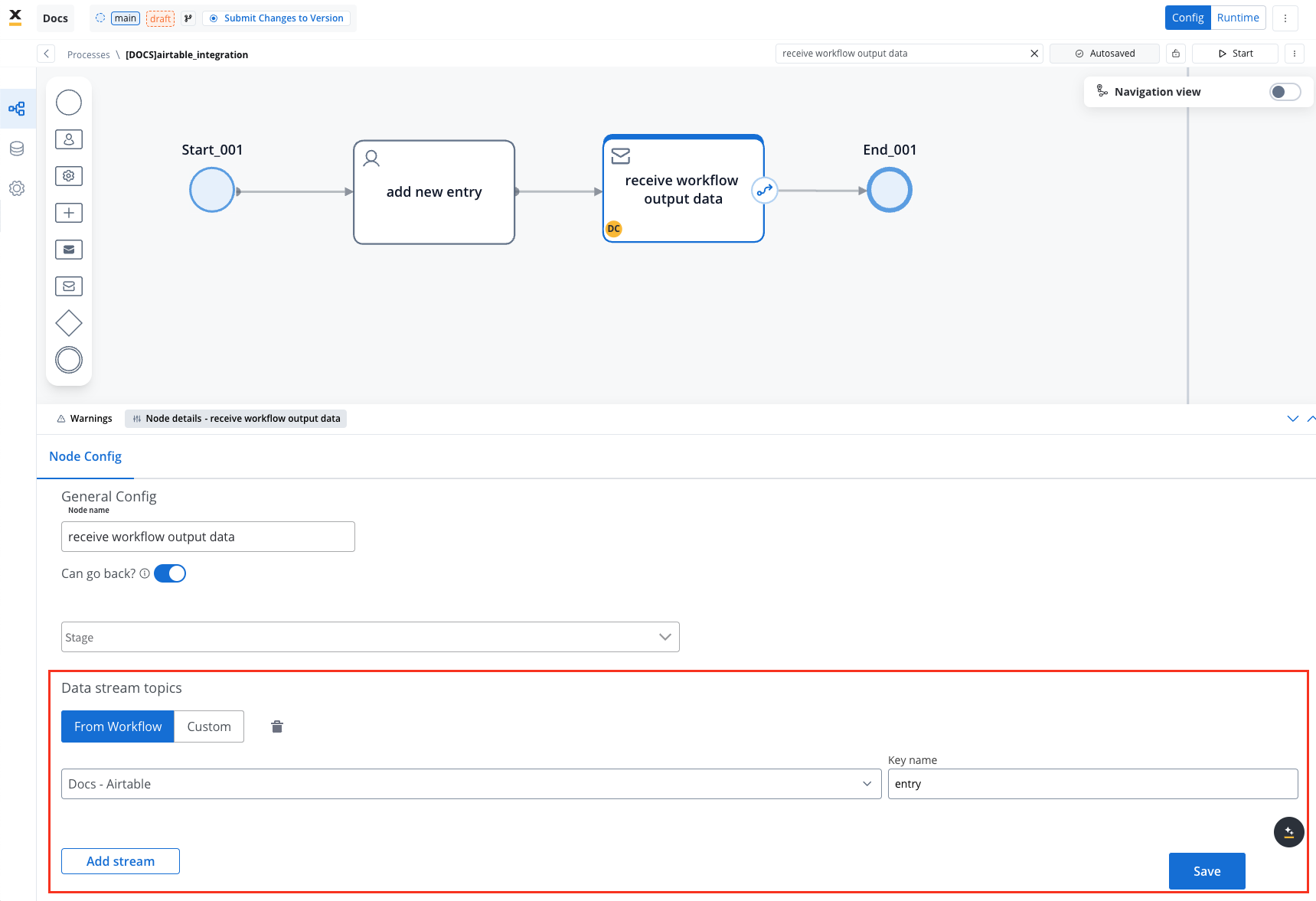
Monitor Workflow and Capture Output
- Use the Receive Message Task to capture workflow outputs like status or returned data.
- Set up a Data stream topic to ensure workflow output is mapped to a predefined key.
Start the integration
- Start your process to initiate the workflow integration. It should add a new user with the details captured in the user task.
- Check if it worked by going to your base in Airtable. You can see, our user has been added.
This example demonstrates how to integrate Airtable with FlowX to automate data management. You configured a system, set up endpoints, designed a workflow, and linked it to a BPMN process.
FAQs
Can I use protocols other than REST?
Can I use protocols other than REST?
How is security handled in integrations??
How is security handled in integrations??
How are errors handled?
How are errors handled?
Can I import endpoint specifications in the Integration Designer?
Can I import endpoint specifications in the Integration Designer?